|
Disclaimer
I am no expert in geodesy or meteorology and the following paragraphs
are just notes from my own solutions to the problems that I
encountered. Some of the statements are unverified. Corrections are
welcome.
|
Lambert conformal conic (LCC) is the map projection of choice when operating one of the popular American numerical weather models MM5 or it’s descendant WRF-ARW in mid-latitudes.
A general approach for finding the value of a model variable on such projected grid given a location specified by latitude and longitude would follow these basic steps:
-
Transform the specified coordinates into the grid’s map projection.
-
Transform the projection coordinates (usually in x/y metres from projection origin) into grid indices (in i/j grid cell sizes from grid origin). By indices I mean decimal, not integers, i.e. [35.1, 64.1] for a point that is a little to the northeast from gridpoint [35, 64] using default WRF LCC grid orientation. This can be done together with the first step.
-
Separating the decimal part and taking
floor/ceilvalues we now have the four bounding gridpoints and coordinates within this square for bilinear interpolation, or we could simply round these values to get the indices of the nearest gridpoint.
As you can see, to extract values from an LCC grid, we need to be able to
transform coordinates from plate carrée (latitude & longitude) to LCC, so the
XLAT and XLONG variables from the wrfout files which provide the
reverse transformation are not of much use in this case. (Actually
they are very useful if you want to—and you definitely should—verify
your transformation.)
The transformation formulae from plate carrée to LCC are much simpler when dealing with a spherical datum rather than with an ellipsoid, and both MM5 and WRF models use this simpler case. However, this fact combined with the way I have seen input data being used all the time (though I cannot generalize that this is the common case) leads to a certain hard-to-find error described further below.
Transforming using MM5 source code
You are likely not to encounter any problems if you transform the coordinates explicitly using the formulae for spherical datum, especially if you follow the original source code like I did at first. My colleague adapted a piece of code from the original Fortran source of MM5’s TERRAIN processor, which isn’t very comprehensible,[1] so I won’t bother including it here. I only have a further adaptation of this code for Java which I believe is still semantically equivalent:
protected double[] lambert_from_spherical(double xlon, double ylat) {
    /*
     * Code partially based on the TERRAIN preprocessor for MM5 v2.0,
     * developed by Yong-Run Guo and Sue Chen, National Center for
     * Atmospheric Research, and Pennsylvania State University
     * 10/21/1993
     */
    double sign, pole, xn, psi1, psi0, xc, yc, flp, r, psx, ylon;
    double xloc, yloc;
    double conv = 57.29578;
    double a = 6370.;

    // This part may be precomputed
    if (MOAD_CEN_LAT < 0.) {
        sign = -1.;
    } else {
        sign = 1.;
    }
    pole = 90.;
    if (Math.abs(TRUELAT1) > 90.) {
        TRUELAT1 = 60.;
        TRUELAT2 = 30.;
        TRUELAT1 = sign * TRUELAT1;
        TRUELAT2 = sign * TRUELAT2;
    }
    if (TRUELAT1 == TRUELAT2) {
        xn = Math.sin(TRUELAT2 / conv);
    } else {
        xn = Math.log10(Math.cos(TRUELAT1 / conv)) -
                Math.log10(Math.cos(TRUELAT2 / conv));
        xn = xn / (Math.log10(Math.tan((45. - sign * TRUELAT1 / 2.) / conv)) -
                Math.log10(Math.tan((45. - sign * TRUELAT2 / 2.) / conv)));
    }
    psi1 = 90. - sign * TRUELAT1;
    psi1 = psi1 / conv;
    if (MOAD_CEN_LAT < 0.) {
        psi1 = -psi1;
        pole = -pole;
    }
    psi0 = (pole - MOAD_CEN_LAT) / conv;
    xc = 0.;
    yc = -a / xn * Math.sin(psi1) * Math.pow(Math.tan(psi0 / 2.) /
            Math.tan(psi1 / 2.), xn);

    // Actual computation for the specified location
    ylon = xlon - STAND_LON;
    if (ylon > 180.) ylon = ylon - 360.;
    if (ylon < -180.) ylon = ylon + 360.;
    flp = xn * ylon / conv;
    psx = (pole - ylat) / conv;
    r = -a / xn * Math.sin(psi1) * Math.pow(Math.tan(psx / 2.) /
            Math.tan(psi1 / 2.), xn);
    if (MOAD_CEN_LAT < 0.) {
        xloc = r * Math.sin(flp);
        yloc = r * Math.cos(flp);
    } else {
        xloc =  -r * Math.sin(flp);
        yloc =  r * Math.cos(flp);
    }

    xloc = xloc - xc;
    yloc = yloc - yc;
    double[] ret = {xloc, yloc};
    return ret;
}
(The code has been translated multiple times and is a little bit messy, but it should just work. All of the procedures described here have been verified to produce correct results.)
The TRUELAT1, TRUELAT2 and STAND_LON values define the LCC
projection and together with the MOAD_CEN_LAT (latitude of the grid
center of the outermost model domain) they also specify projection
coordinate origin. All of these values are available as global
attributes of the WRFOUT/MMOUT files.
Using a generic projection library
So you’d rather use a well-known library like PROJ.4 instead of further translating an unverifiable piece of code from some webpage into your language of choice? Good for you, but there is a catch.
As you can verify, the LCC projection used by WRF and MM5 can be defined in PROJ.4 as
+proj=lcc +lat_1=TRUELAT1 +lat_2=TRUELAT2 +lat_0=MOAD_CEN_LAT
    +lon_0=STAND_LON +a=6370 +b=6370 +towgs84=0,0,0 +no_defs
i.e. a Lambert conformal conic projection with two standard parallels on a spherical datum defined by taking the WGS84 ellipsoid and replacing it with a sphere of 6370km radius. Pretty straightforward.
The catch lies in the fact that the simple spherical LCC transformation equations will work for transforming between this projection and plate carrée of the same sphere. If instead you tell PROJ.4 to convert between your LCC and the standard WGS84:
+proj=latlong +ellps=WGS84 +datum=WGS84 +no_defs
you will get errors of up to tens of kilometers (in mid-latitudes). Why? Because WGS84, i.e. what almost everybody assumes when being presented with unqualified latitudes and longitudes,[2] is an ellipsoid and it uses geodetic—not geocentric—latitudes. If you don’t know what these mean, I urge you to read the definition before proceeding further.
The root of all problems lies in the practice when all the georeferenced inputs to the numerical model—orography, landuse and initial and boundary conditions from the GFS global model—all of which are referenced in WGS84, are being fed to the model directly as if they were already in the model’s spherical coordinates, while in theory they should first be transformed from geodetic to geocentric latitudes.
I have no idea how common this practice is. I only know that my colleagues who started operating MM5 many years ago using only the official documentation ended up with this configuration for all of our models (without knowing about the problem) and that an unrelated team I have spoken with had exactly the same problem. My theory for why this hasn’t been discussed much yet is that until you start doing absolute coordinate transformations with PROJ.4 or similar, every input and output data will actually match, so you probably won’t have any problems at all.
So, in case you are in the same situation, how should you transform your model coordinates using PROJ.4? Simply use the LCC definition above and transform from/to the respective spherical latitudes and longitudes as defined here:
+proj=latlong +a=6370 +b=6370 +towgs84=0,0,0 +no_defs
In case you need to further transform your coordinates to any other projection, and you want to be sure, I’m afraid you will have to do the transform in two steps:
-
Transform from model LCC to spherical lat/lon.
-
Take these lat/lons as if they were WGS84 and transform them to your desired projection.
Reverse the process if necessary. I haven’t found a projection specification that could trick PROJ.4 into doing this in one step, but maybe you will. If you do, please don’t forget to write me.
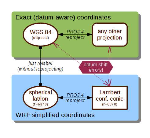
Edit: coordinate transformation diagram
A picture is worth a thousand words, so I made this diagram which may come handy when using e.g. a GIS software for manipulating georeferenced WRF inputs and/or outputs.